

For hollow structural section (HSS) connections, welds can be designed either to achieve the capacity of the connected branch member wall or to be “fit for purpose” (i.e. to resist the forces present in the branch member). The latter approach typically results in smaller, more economical welds, but it requires the use of weld effective properties. Weld effective properties account for the inherent non-uniform loading of the weld perimeter in an HSS joint, which is primarily due to differences in the relative flexibility of the chord member in the direction of the applied load from the branch.
By Dr. Kyle Tousignant, Assistant Professor, Department of Civil & Resource Engineering, Dalhousie University
Over the last 30 years, research has been conducted to determine weld effective properties for rectangular hollow section (RHS) connections, including gapped and overlapped K-connections, T-, Y- and X- (or Cross-) connections, and moment-loaded T-connections. In 2010, recommendations based on this research were adopted as design rules in Section K4: “Welds of Plates and Branches to RHS” of AISC 360-10 (now Section K5, in AISC 360-16). In Canada, similar methods to calculate weld effectiveness (i.e. weld effective properties for RHS connections) are available in Packer & Henderson (1997). These are referenced in Part 3: “Connections and Tension Members” of the 11th edition of the CISC Handbook. However, AISC 360 and Packer & Henderson (1997) are both silent concerning weld effective properties for CHS connections. This is because – until recently – no supporting research had been performed.
Experimental Testing
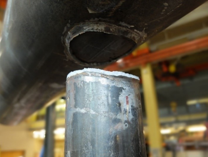
With the financial support of CISC and the federal government, and in-kind support from Walters Group and Atlas Tube, an experimental testing program was carried out to establish weld effective lengths for axially loaded CHS T-, Y-, and X-connections. A set of 12 connection test specimens, fabricated from large-size ASTM A500 dual-certified Grade B/C HSS, were designed to be “weld critical” (i.e. to fail by weld fracture) under axial tension applied to the branches, as shown in Figure 1a. The chord members were HSS 10.75 × 0.500 and HSS 16.00 × 0.500, with branches (inclined at 90° or 60° to the chord) selected to obtain branch-to-chord width ratios (β) ranging from 0.25 to 0.47 and branch-to-chord thickness ratios (τ) ranging from 0.60 to 0.99. Welding procedure specifications were developed (in conjunction with trial sectioning) to achieve minimal but adequate root penetration, and a professional fabricator was employed to deposit the fillet welds around the branches. The test welds were laid using a semi-automatic flux-cored arc welding process with a CO2 shielding gas.
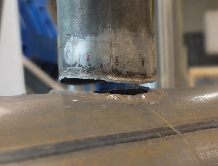
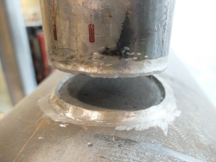
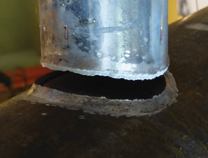
Prior to testing, the fillet welds were ground to a triangular shape, as shown in Figure 1b, and careful measurements were made of their geometric and mechanical properties. The test specimens were instrumented with strain gauges adjacent to welds and loaded to failure by a 2700-kN capacity universal testing machine, as shown in Figure 2. All 12 of the specimens performed as intended, with failure occurring by fracture along a plane through the fillet weld. Several typical examples of weld fractures from the testing program are shown in Figure 3.
The strain gauges installed on the specimens adjacent to the welds indicated non-uniform loading of the branch (and hence the weld), which (a) peaked around the saddle points (see Figure 1b), and (b) was more pronounced in the specimens with high β and slender chords (i.e. reflected by high chord diameter-to-thickness, or D/t, ratios).
FIGURE 1: CHS-to-CHS X-connection test specimens
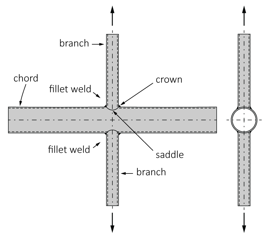 | 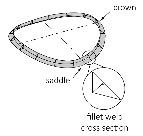 |
(a) CHS-to-CHS X-connection | (b) weld geometry |
FIGURE 2: Testing arrangement
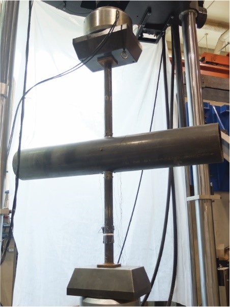
FIGURE 3: Weld fractures
 |  |
 |  |
 |  |
Finite Element Modelling
Non-linear finite element (FE) models, with weld fracture, were validated against the results of the experimental tests, and an FE parametric study was performed to extend the test database. The FE parametric study consisted of 256 CHS-to-CHS X-connections, with wider variations in β, D/t, τ and the branch inclination angle (θ) compared to the experimental tests (namely 0.10 ≤ β ≤ 0.50, 10 ≤ D/t ≤ 50, 0.20 ≤ τ ≤ 1.00, and 60° ≤ θ ≤ 90°). These parameters were kept within the limits that allow fillet welds, per AWS D1.1. As planned, all 256 of the FE connection models showed failure occurring – again – by weld fracture.
Through this experimental and FE research, it was found that fillet weld effective lengths in CHS-to-CHS X-connections are (a) primarily a function of β and D/t and (b) become larger (relative to the total weld length) as β and D/t become smaller. Specifically, the weld effective lengths ranged from 0.58 to 1.0 times the total weld length within the parameter range studied, and welds in connections with β(D/t) ≤ 8 were 100% effective. The analytically observed “weld-effective-length trends” in CHS-to-CHS X-connections will be prevalent in CHS-to-CHS T- and Y-connections of similar geometries (under branch axial loading), and apply regardless of weld type (e.g. fillet weld or partial joint penetration groove weld) if the welds are designed to be “fit for purpose”. For connections with partially effective weld lengths, the “effective weld” is illustrated in Figure 4.
FIGURE 4: Proposed effective weld for CHS-to-CHS T-, Y-, and X-connections
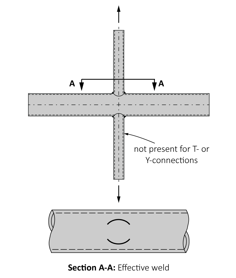
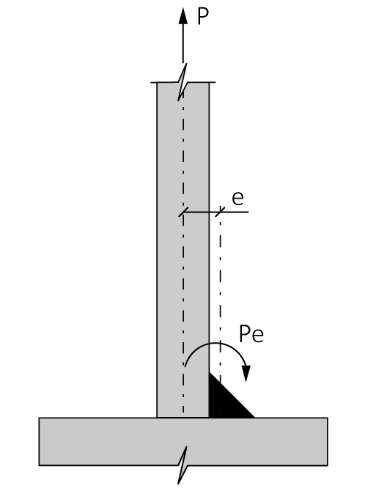
FIGURE 5: Local bending about the axis of a single-sided fillet weld
Design Recommendations
An effective-length design method for welds in CHS-to-CHS T-, Y-, and X-connections has now been proposed for AISC 360. In AISC 360-22, the so-called “directional strength-increase (or sinθ) factor” will be allowed for single-sided fillet welds that connect CHS branches to base plates, cap plates and HSS chords (and hence for CHS-to-CHS connections). The proposed design method has therefore been verified to meet AISC’s target reliability index (β+ ≥ 4.0 for connections, per Section B3.1 of the AISC 360 Commentary) in conjunction with using the “sinθ factor” for fillet welds. On the other hand, CSA S16-19 will not permit the “sinθ factor” for single-sided fillet welds that connect elements in tension (including HSS branches). This is based on recent experiments and FE analysis on single-sided fillet welds around the ends of HSS that (a) confirmed bending about the weld axis occurs when the HSS is in tension, and (b) showed, in some cases, that the welds did not develop the same “strength increase” at failure predicted by the “sinθ factor”.
Next Steps
The next step in this ongoing research is to clearly determine the factors that affect the strength of single-sided fillet-welds in HSS and non-HSS connections. This will be critical to potentially alleviate the CSA S16-19 restriction on the “directional strength-increase factor” and improve steel fabrication economy. With the financial support of CISC and the federal government, a research project with these aims, entitled “Design of Single-Sided Fillet Welds in Tension”, will be carried out at Dalhousie University beginning in September 2019.