Seismic forces in a building structure must be transmitted from the roof and floor diaphragms to the vertical seismic force-resting system (and the foundations).
In a steel-framed structure, they are typically transmitted via horizontal members, such as beams, joists and trusses, serving as collectors. Thus, the forces are typically transferred in shear between the sheet steel roof deck and the roof diaphragm collectors, or the floor deck-slab and the floor diaphragm collectors. While CSA Standard S16 does not dictate specific means for diaphragm-collector shear transfer, this article briefly summarizes the most common methods used in construction.
Roof diaphragms
The most common roof structures feature a sheet steel roof deck on open-web steel joists and wide-flange girders and spandrel beams. Figure 1 shows the plan view of a roof example of a single storey building. The vertical braced bents are shown in red, whereas the main collectors are in blue. Typically, the roof deck is connected to the OWSJs and spandrel beams by means of arc spot welds or screws. The girders, however, must be lowered to accommodate the joist shoes. Collector shear transfer connectors matching the joist shoe depth are therefore required to bridge the gap. See Figure 2.
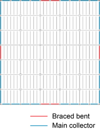
Figure 1
Roof Diaphragm
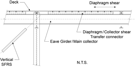
Figure 2
Girder-Collector Shear Transfer
Floor Diaphragms
When floor diaphragm forces are relatively low and do not exceed the factored shear resistance of sheet steel floor deck alone, the above-mentioned roof diaphragm shear transfer method may be adequate. For larger shear forces, particularly when the design includes the contribution of the concrete cover slab for diaphragm shear resistance, welded-stud shear connectors are commonly used to transfer the diaphragm shear between the deck-slab diaphragm and the main collectors. For example, in the floor as shown in Figure 3, welded studs can be placed on the main collector beams and girders as shown in blue.
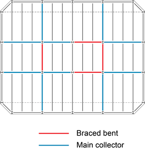
Figure 3
Floor Diaphragm
Welded stud shear connectors may also be placed on the beams within the vertical seismic force-resting system (identified as red lines in Figure 3) with several exceptions. They are not permitted on beams in chevron moderately ductile and chevron limited-ductility concentrically braced frames that are not designed to be capacity-protected members. Where these beams in low-rise frames are permitted to be designed to serve as yielding elements, the presence of shear studs inflates the flexural capacity of these beams. Similarly, they are not permitted within the protected zones in ductile eccentrically braced frames in order to avoid inflating the capacity of the ductile links. Also, welded studs should not be placed in the protected zones in ductile, moderately ductile and limited-ductility moment-resisting frames, unless the studs formed a part of the tested assembly that serves to qualify the use of the beam-to-column connections in the construction.