QUESTION: (SUMMER2014) I find the design requirements for pin-connected tension members as stipulated in CSA S16-09 very difficult to satisfy. They appear to mandate the use of eyebars. Have I missed something?
ANSWER: The requirements in CSA S16-09 aim to ensure a gross-section yielding ultimate limit state and are therefore quite restrictive. New requirements have been introduced in CSA S16-14. This new provision improves design versatility considerably.
QUESTION: (SPRING2014) When only one leg of an angle tension member is attached to its end supports, with longitudinal fillet welds, how do I determine if shear lag is important and how is it accounted for?
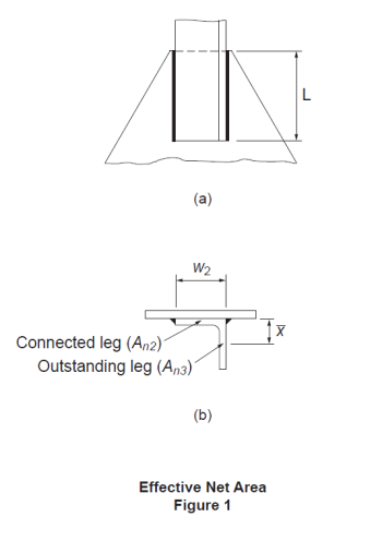
ANSWER: The effect due to shear lag in a tension member is usually accounted for by means of an effective area method. For weld-connected members, Clause 12.3.3.3 of CSA S16-09 applies to members of various cross sections in general. The cross-section area of the angle is divided into two components, i.e., the attached leg and the outstanding leg. Figure 1(a) shows an angle connected by a pair of longitudinal welds of length, L. For the attached leg, shear lag is a factor when L ≤ 2w2. In accordance with Clause 12.3.3.3 (b)(ii) and (iii), its effective net area, An2, as shown in Figure 1(b), is determined based on the weld configuration and, for short welds, also the leg thickness. The effective net area of the outstanding leg, An3, is calculated according to Clause 12.3.3.3(c). Its shear lag effect is given as a function of the ratio of the eccentricity of the weld with respect to the centroid of the outstanding leg, x, to the weld length, L. Then the tensile resistance of the member is calculated in accordance with Clause 13.2(a)(iii) using the total effective net area of the angle section, Ane = An2 + An3.Further information may be found in the CISC Commentary on CSA S16-09 in Part 2 of the Handbook of Steel Construction.

QUESTION: (SPRING2011) Is knife edge angle connection the right choice for axial tension or combined shear and axial tension?
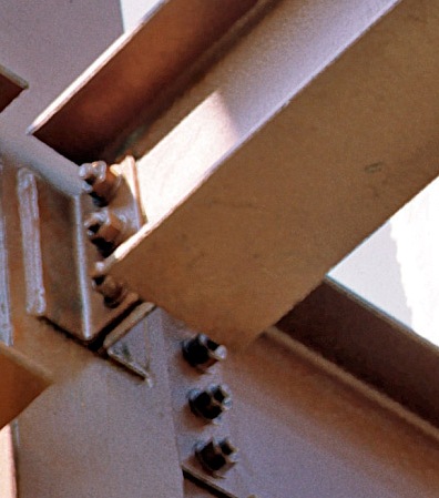
ANSWER: Knife edge angle connection, commonly known as knife connection, is a very common type of beam shear connection. It features a pair of angles that are typically welded to the column in the shop and bolted to the beam web in the field (Figure 1). While knife connection serves as a popular beam shear connection, its use is not recommended where significant axial tensile forces are to be transmitted, such as end connections for braced frame members and collectors that are subjected to significant axial tensile forces. Research studies, reported in the reference below, have demonstrated that knife connection exhibits limited axial tensile resistance. In the reference below, the test results of several other common beam shear connections subjected to combined shear and axial forces were also reported.
Reference: Guravich, S. J. and Dawe, J. L. 2006. Simple beam connections in combined shear and tension. Canadian Journal of Civil Engineering. 33(4): 357-372.

