
A typical concentrically braced frame featuring X-bracing and subject to a lateral load “P” is illustrated in Figure 1. The compression brace (C) is susceptible to in-plane buckling, although out-of-plane buckling is the more common governing condition. In the following discussion, it is assumed that the diagonal braces are continuous and connected at the intersection point.
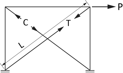
Figure 1
Diagonal Braces in X-Bracing Configuration
The question naturally arises as to what effective length KL should be used to determine the factored resistance of the compression brace. Should one use K = 1.0 or 0.5, or some other value? And what is the restraining effect of the tension brace (T)? The cases involving braced frames subject to wind and seismic loading will be addressed separately.
1) Wind Loading
Braced frames with X-bracing subject to wind loading have been examined by André Picard and Denis Beaulieu (1987, 1988). They concluded that the effective length of the compression diagonal is half the full member length (i.e. K = 0.5). However, the study was based mostly on elastic buckling and on the assumption that no out-of-plane displacement occurs at their point of intersection.
The inelastic stability of X-bracing was studied by Lui and Zhang (2013), who found that the restraining effect of the tension diagonal depends on a quantity termed the “lateral transition stiffness”. The case of an unbraced compression diagonal is illustrated in Figure 2(a), corresponding to its first (symmetric) buckling mode. For this condition, Pmax/Po = 1, where Pmax is the compressive diagonal resistance and Po is the compressive diagonal resistance of the unbraced configuration (K = 1).
As the tension member stiffness increases up to the transition stiffness, the compression diagonal is partially braced and fails in an intermediate buckling mode. As illustrated in Figure 2(b), the point of intersection exhibits an out-of-plane displacement, and Pmax/Po falls between 1 and 4. Finally, when the transition stiffness value is reached, the compression diagonal is fully braced and fails in its second (anti-symmetric) buckling mode, as shown in Figure 2(c). The ratio Pmax/Po reaches its maximum value of 4, and any further increase in tension member stiffness has no effect on the compressive resistance.
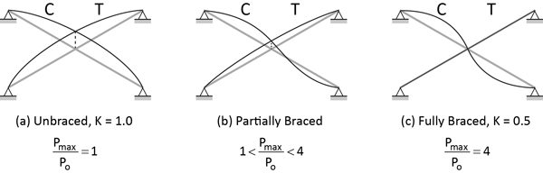
Figure 2 Out-of-Plane Buckling Modes
2) Seismic Loading
In braced frames subject to seismic loading, the use of an effective length factor, K = 0.5, remains the current practice. As stated in the CISC Commentary on CSA S16-14, Clause 27.5.3.1:
When determining the brace slenderness, the actual support conditions of the braces must be accounted for in determining KL. (…) For X-bracing, when the brace end connections are detailed with single vertical gussets, K can be taken equal to 0.4 and 0.5 for in-plane and out-of-plane buckling, respectively, with L taken as the length between the anticipated plastic hinge locations at the ends of the bracing members. (…) Caution must be exercised when one of the braces is interrupted at the brace connection point of X-bracing, as this can reduce the stiffness of the tension brace supporting the compression brace and/or lead to local instability of the connecting elements.
3) References
Lui, E.M. and Zhang, X. 2013. Stability Design of Cross-Bracing Systems for Frames. Engineering Journal, AISC, 3rd Quarter.
Picard, A. and Beaulieu, D. 1987, Design of Diagonal Cross Bracings, Part 1: Theoretical Study. Engineering Journal, AISC, 3rd Quarter.
Picard, A. and Beaulieu, D. 1988, Design of Diagonal Cross Bracings, Part 2: Experimental Study. Engineering Journal, AISC, 4th Quarter.