A design example is presented to illustrate the use of charts in Module 2 of the CISC Steel Design Series, Bolt Groups Subjected to an Eccentric and Inclined Point Load. A double column bracket must be designed to support a factored vertical load of 500 kN applied at a horizontal distance of 400 mm from the bolt group centroid. A horizontal factored load of 100 kN, which can act to the left or the right, is also applied at a vertical distance of 275 mm above the centroid. A double-row group consisting of twelve ¾ inch A325 bolts per column flange is provided with a gauge dimension of 160 mm and a pitch of 80 mm (see Figure 1). Find the factored resistance of the bolt group assuming a bearing-type connection.

Figure 1
Solution:
Assuming each column flange receives one-half of the applied loads, the resultant factored load per column flange is:
Pf = (2502 + 502) 0.5 = 255 kN
The inclined load angle is:
θ = tan-1 (50 / 250) = 11.31o
The horizontal load can act in either direction; we’ll consider the tensile force first:
L1 = 400 + 275 tan 11.31o = 455 mm
By inspection, the value of L when the horizontal force acts to the left, L2, is shorter and does not govern.
The bolt configuration corresponds to Figure 3e in SDS-2 (Figure 2 herein). Using the chart and interpolating between the curves for L = 400 and 500 mm, we obtain the value of coefficient C ≈ 3.5.
Vr = 113 kN (Table 3-4 in the Handbook 11th Edition, single shear, threads excluded)
The bolt group capacity is:
3.5 x 113 = 396 kN per side > 255 kN
The connected parts should be proportioned to resist the effects due to the applied forces in accordance with CSA S16-14. Such calculations are not shown here.
The chart can be used to design the bracket as a slip-critical connection, if required.
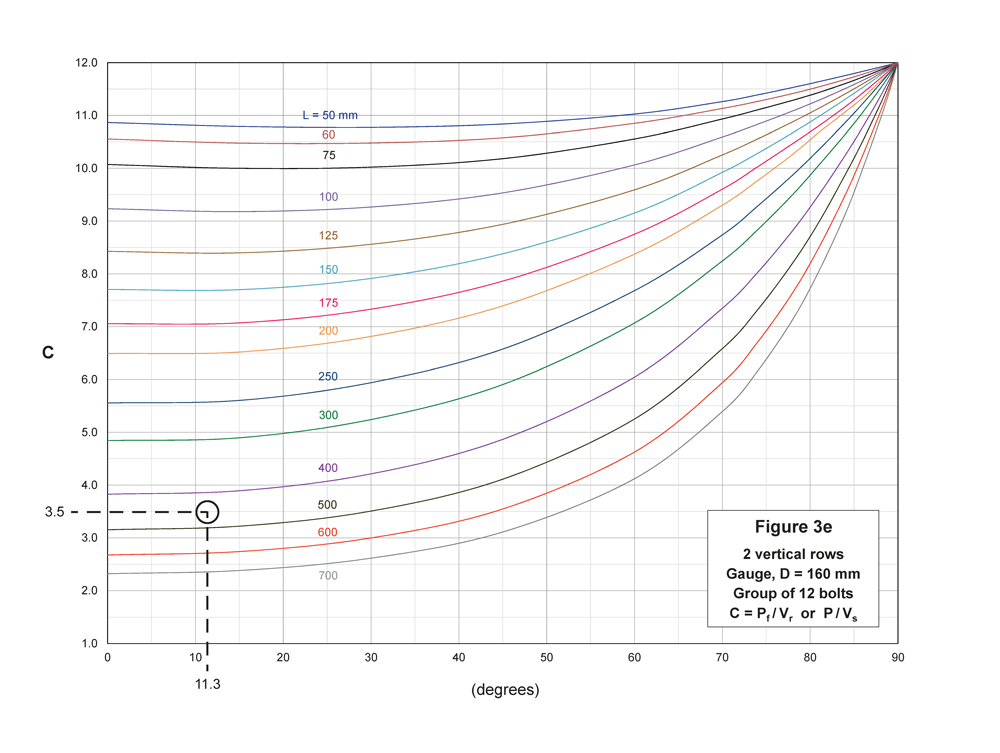
Figure 2