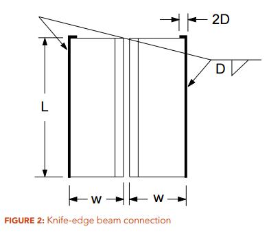
QUESTION: (2015) For a knife-edge beam shear connection with double-angle welded to the support (Figure 2), can the top edge of the angles also be welded in order to increase the weld capacity?
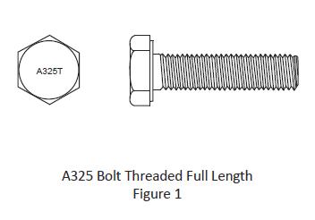
QUESTION: (FALL2015) I recently came across some fully threaded A325 bolts in the connections of a building structure. Are these bolts permitted? Do they have the same resistances versus bolts with regular thread length? How are they identified after installation? Do they offer any benefit?
QUESTION: (WINTER2014/2015) How is the shear resistance for gross section of gusset plates determined – should I use Clause 13.4.3 of S16-09 on webs of flexural members not having two flanges or Clause 13.11 on block shear? They give very different results.
ANSWER: Neither. Clause 21.12, “Connected elements under combined tension and shear stresses”, a new clause introduced in CSA S16-14, covers this.
QUESTION: (SUMMER2014) Are bolted moment connections used in a canopy structure required to be slip critical? My question relates to a situation where slip critical connections are not required for deflection control. I have many years of connection design experience but seldom had to provide slip-critical connections for wind-load resisting braced bents or moment frames.
ANSWER: The key question here is whether fatigue is a consideration; will the structure be subjected to repetitive loading and stress reversal? A relatively light canopy type of structure subjected to gusty local wind load may experience stress reversal and a significant number of load cycles to warrant such assessment. The judgement rests with the engineer responsible for the design of the structure. Fatigue design is covered in Clause 26 of S16.
QUESTION: I find the design requirements for pin-connected tension members as stipulated in CSA S16-09 very difficult to satisfy. They appear to mandate the use of eyebars. Have I missed something?
ANSWER: The requirements in CSA S16-09 aim to ensure a gross-section yielding ultimate limit state and are therefore quite restrictive. New requirements have been introduced in CSA S16-14. This new provision improves design versatility considerably.
QUESTION: (SPRING2014) When only one leg of an angle tension member is attached to its end supports, with longitudinal fillet welds, how do I determine if shear lag is important and how is it accounted for?
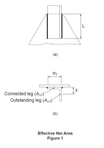
ANSWER: The effect due to shear lag in a tension member is usually accounted for by means of an effective area method. For weld-connected members, Clause 12.3.3.3 of CSA S16-09 applies to members of various cross sections in general. The cross-section area of the angle is divided into two components, i.e., the attached leg and the outstanding leg. Figure 1(a) shows an angle connected by a pair of longitudinal welds of length, L. For the attached leg, shear lag is a factor when L ≤ 2w2. In accordance with Clause 12.3.3.3 (b)(ii) and (iii), its effective net area, An2, as shown in Figure 1(b), is determined based on the weld configuration and, for short welds, also the leg thickness. The effective net area of the outstanding leg, An3, is calculated according to Clause 12.3.3.3(c). Its shear lag effect is given as a function of the ratio of the eccentricity of the weld with respect to the centroid of the outstanding leg, x, to the weld length, L. Then the tensile resistance of the member is calculated in accordance with Clause 13.2(a)(iii) using the total effective net area of the angle section, Ane = An2 + An3.
Further information may be found in the CISC Commentary on CSA S16-09 in Part 2 of the Handbook of Steel Construction.
QUESTION: (SPRING2013) Clause 13.11 of S16-09 appears to have omitted the check for shear rupture of net section. What has happened to the shear rupture failure mode and where is the provision for pure shear rupture?
ANSWER: The equation provided in Clause 13.11 of S16-09, as shown below, consists of both the tension and shear contributions to the block shear resistance of a bolted joint.
The first term accounts for the resistance against tension whereas the second term represents the shear component. An example is shown in Figure 2a. The ultimate resistance of block shear is attained when the net section(s) subjected to tension reaches its fracture capacity. Typically, the deformation associated with this tensile capacity is too small to mobilize complete shear rupture at the same time. As recommended by Driver et al, the shear component is based on 0.6 times the mean value of Fy and Fu in this calculation. It should be noted that the gross area in shear, Agv(taken as the area of the plane(s) tangential to the bolt holes), is used in this calculation.Pure shear rupture, as shown for the example in Figure 2b, should also be considered. The second term of the equation above covers it. In the absence of the above-mentioned deformation incompatibility, larger shear resistance can be attained for pure shear rupture. However, Clause 13.11 provides a simple solution.
Figure 2a: Block Shear Figure 2b: Shear Rupture
QUESTION: (SPRING2013) How is the strength reduction factor for multi-orientation fillet welds, Mw, applied? Please show an example.
ANSWER: In the weld configuration shown in Figure 1, 8-millimetre fillet welds are used, Xu = 490 MPa and the plate is G40.21 350W steel. Note that the farside plate is thicker.
In accordance with CSA S16-09 Clause 13.13.2.2:
Vr = 0.67 ɸw Aw Xu (1.00 + 0.50 sin1.5 θ) Mw
where:θ = angle of axis of weld segment with respect to the line of action of the applied force
Mw = strength reduction factor for multi-orientation fillet welds
a) Weld segment at θ = 60o:
Orientation of the weld segment under consideration: θ1 = 60o
Orientation of the weld segment in the joint that is nearest to 90o: θ2 = θ1 = 60o
![]()
Orientation of the weld segment in the joint that is nearest to 90o: θ2 = 60o
Vr = 2 x 0.67 x 0.67 x 8 x 100 x 0.707 x 0.490 (1.00 + 0.50 sin1.5 0o) 0.895
+ 0.67 x 0.67 x 8 x 120 x 0.707 x 0.490 (1.00 + 0.50 sin1.5 60o) 1.00
= 2 x 111 + 209 = 431 kNFor matching electrodes, the base metal resistance need not be checked
Figure 1: Strength Reduction for Multi-Orientation Fillet Welds
QUESTION: (FALL2012) When designing bolted connections, are seismic loads considered to be static or cyclic?
ANSWER: The Seismic Corner article entitled “Bolted Connections for Seismic Applications” in CISC publication, Advantage Steel No. 31 (Summer 2008), outlined the requirements for bolted connections for seismic applications in accordance with S16-01. The article is available at: https://cisc-icca.ca/ciscwp/product/advantage-steel-no-31/
In NBC 2010 and S16-09, the building height restriction for Conventional Construction where the specified short-period spectral acceleration, IEFaSa(0.2), exceeds 0.35 has been increased. The above mentioned requirements for bolted connections also apply to these taller structures of Conventional Construction.
QUESTION: (FALL2012) When designing fillet welds in shear, is it necessary to check the base metal resistance at the fusion face?
ANSWER: In accordance with S16-01, the shear resistance of fillet welds is taken as the lesser of: (a) the weld metal resistance given as a function of the ultimate strength of the electrode, Xu , and the effective throat area, Aw and (b) the base metal resistance given as a function of its tensile strength, Fu , and the fusion face area, Am. Unless over-matched electrodes are used the base metal resistance does not govern the design of longitudinally loaded joints. However, when the weld orientation approaches the transversely loaded case the base metal resistance governs due to the significantly larger weld metal resistance.In S16-09, it is no longer necessary to check the base metal strength at the fusion face when matching electrodes are used (Clause 13.13.2.2). Research studies conducted at the University of Alberta have demonstrated that the base metal resistance determined using the virgin strength of the base metal does not represent the shear resistance. The researchers pointed to the fact that the properties of the base metal at the fusion face are influenced by intermixing of the weld and base metals. Unless over-matched electrodes are used, base metal resistance at the fusion face need not be checked, regardless of weld orientation.For a list of matching electrodes for CSA G40.21 steels, see Table 4 in S16-09.
QUESTION: (SPRING2012) When wide-flange purlins are also subjected to significant axial tension, which is transmitted by connecting the bottom flange to the supports with two transverse lines of high strength bolts, how do I account for shear lag? Specifically, should the effective net area, Ane, be taken as 0.75An, as provided in Clause 12.3.3.2 (c) (ii) of S16-09?
ANSWER: The approach as you described is unconservative. In this situation, the effect of shear lag is more severe than the case for angles connected by one leg with two transverse lines of fasteners. Hence Ane < 0.60An. On the other hand, the lower bound for Ane may be taken as Anf, where Anf is the net area of the connected flange alone. Therefore, Ane should lie somewhere between Anf and 0.60An.
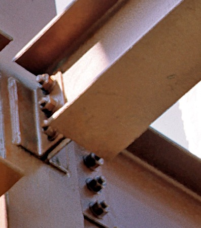
QUESTION: (SPRING2011) Is knife edge angle connection the right choice for axial tension or combined shear and axial tension?
ANSWER: Knife edge angle connection, commonly known as knife connection, is a very common type of beam shear connection. It features a pair of angles that are typically welded to the column in the shop and bolted to the beam web in the field (Figure 1). While knife connection serves as a popular beam shear connection, its use is not recommended where significant axial tensile forces are to be transmitted, such as end connections for braced frame members and collectors that are subjected to significant axial tensile forces. Research studies, reported in the reference below, have demonstrated that knife connection exhibits limited axial tensile resistance. In the reference below, the test results of several other common beam shear connections subjected to combined shear and axial forces were also reported.
Reference: Guravich, S. J. and Dawe, J. L. 2006. Simple beam connections in combined shear and tension. Canadian Journal of Civil Engineering. 33(4): 357-372.